Product Review: AMT PostPro SFX Vapour Smoothing Machine
Our review of the AMT PostPro SFX Vapour Smoothing Machine shows how this system delivers consistent, injection-moulded finishes on 3D…


Our review of the AMT PostPro SFX Vapour Smoothing Machine shows how this system delivers consistent, injection-moulded finishes on 3D…

SGD 3D partnered with ARX Security to produce detailed scale models of their modular barrier systems using SLS 3D printing…
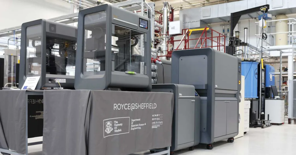
Education 3D printing in Sheffield is transforming how students learn engineering. By combining CAD design, 3D scanning, and hands-on manufacturing,…